Cameras define how the scene is viewed in the screen, as every other object they have a position and rotation, and can control where to draw content on the screen and can have post-processing effects attached.
A scene can use multiple cameras at the same time, camera have a draw order preference attached to them, used to decide which one to render from first. Cameras can be added from the object add bar.

A perspective camera is used to draw objects with a perspective projection. A perspective projection is a 3D where depth can be easily perceived by the used.
In perspective cameras the following parameters can be configured:
FOV (Field-of-view): Angle in degrees used to control the camera field of view.
Orthographic cameras are used to draw object with a orthographic projection. A orthographic proection is a 2D projection where its impossible for the used to perceive distance, objects far away from the camera appear to have the same size as the ones closest to it.
In orthographic cameras the following parameters can be configured:
Size: Used to control how much the camera can see inside the scene
Resize mode: Defines how the camera is resized when the window size changes, if set to horizontal mode, the vertical size of the camera stays the same and the horizontal size changes on resize, if set to vertical mode, the horizontal stays locked and the vertical size changes.
In the demo bellow we can see booth a perspective camera (on the left) and a orthographic camera (on the right) in action.
To try this example in the editor you can download the project file or open it on the Web Editor.
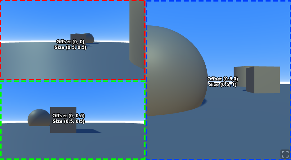
The zone on the screen where the camera draws can be controlled using the viewport attributes. This allows for multiple cameras to be displayed at the same time on one screen.
Position: Normalized coordinates used to select where the draw zone starts (bottom left corner). Ranges from 0 to 1.
Size: Normalized coordinates used to define the size of the draw zone. Ranges from 0 to 1.

In the example bellow the booth cameras have a viewport of (1.0, 0.5) this means that the cameras ocupy 100% of the screen in the horizontal and half the screen in the vertical. And position for the camera on the bottom (0,0), and (0, 0.5) for the top camera. These positions are relative to the bottom left corner of the viewports. The bottom camera start on the bottom left of the screen and the top camera starts at 50% of the vertical size of the screen.
To try this example in the editor you can download the project file or open it on the Web Editor.
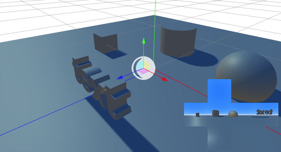
Cube cameras are composed of 6 internal perspective cameras aligned to capture an entire 360 projection of the scene.
These type of cameras are useful for material effects that require access to information of the surroundings (e.g reflections, refraction). These can be programmatically attached to the scene (as background) or to materials (as environment map).
